展示全部
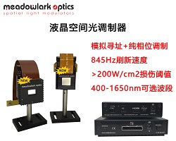
会产生不同的光程差,从而实现相位的调制。 涡旋光束是具有连续螺旋状相位的光束,即光束的波阵面是旋涡状的,具有奇异性,其光束的中心是一个暗核,此处的光强为零,相位无法确定。对于光学涡旋,特别是具有复杂拓扑结构的光学涡旋,可以通过SLM获得。本文利用Meadowalrk Optics公司的P1920型液晶空间光调制器产生了不同拓扑荷值的涡旋光。 Meadowlark Optics公司的空间光调制器采用独有的模拟寻址技术,使相位的稳定性更出色。本文用到的P1920型SLM具有高分辨率,高衍射效率,高填充因子,高损伤阈值,高灰度等级(4096/12bits),低相位纹波(0.5-1%)等性能著称。 ...
面形变来改变光程差,空间光调制器具有更高的调制精度。液晶空间光调制器在自适应光学领域的典型应用1、大气湍流模拟器鉴于液晶空间光调制器的亚毫秒液晶响应速度、高像素密度、高相位调制精度、相位编程实时控制等特点,因此可以很好的模拟大气湍流随机性,变化速度快等特点。液晶空间光调制器特别适合高精度可控湍流模拟,为大气湍流的研究提供了非常有力的支撑。目前实现大气湍流模拟的方法主要有:Zernike多项式法、功率谱反演法等。下图为运用Meadowlark Optics公司的256*256型液晶空间光调制器做的大气湍流模拟结果。 2、 波前矫正器液晶波前矫正器作为一种高单元密度的新型波前矫正器件,通过相息图的 ...
会产生不同的光程差,从而实现相位的调制。Meadowlark Optics公司的空间光调制器采用独有的模拟寻址技术,使相位的稳定性更出色。Meadowlark Optics(原BNS)致力于空间光调制的研发已有40多年的历史了,最早主要与美国军方合作。其空间光调制器技术处于世界领先水平,以高液晶响应速度(up to 500Hz),高衍射效率,高填充因子,高损伤阈值等性能著称。02 空间分辨率液晶空间光调制器(LCos)是由二维的像素阵列组成的,Meadowlark Optics公司可以提供的空间分辨率有1920x1152、512x512、1x12288等系列。其中 1920x1152系列SLM ...
果像差引起的光程差,即波像差为W,那么对于一个像差很小的光学系统来说中心点亮度S.D.与波像差W之间有相对简单的关系,即S.D.=1- k^2 ¯(W^2 )利用这种关系和上述S.D. >= 0.8的判据,就可以决定像差的最佳校正方案和像差的公差。Strehl提出的中心点亮度S.D.>= 0.8的判据是评价小像差系统成像质量的一个比较严格而又可靠的方法,但是缺点是计算起来相当复杂,不便于实际应用。瑞利判断瑞利判断:实际波面与参考球面之间的最大偏离量,即波像差不超过1/4波长时,此时实际波面可认为是无缺陷的。该判断提出两个标准,即:有特征意义的是波像差的最大值;波像差最大值的容许量不 ...
两路光束由于光程差会产生一条干涉条纹,通过所谓的条纹计数法即可得到被测位移的大小)。这是一种直流光强检测的方法,对激光器的频率稳定度和测量环境要求很高,其中光学元器件是造成元器件的非线性误差的重要因素之一,原因一般为安装调试复杂,还有调整内部玻片的角度,而且单频干涉原理下抗干扰能力不强,受环境影响较大。零差干涉仪示意图2 激光外差干涉:外差干涉法是较为流行的一种检测方式,其原理同样基于迈克尔逊干涉仪,但采用一定频差f的双频光束作为载波信号的干涉仪,也就是所谓的双频干涉。其原理为当激光探测到一个物体的位移时,由于多普勒效应,被物体散射或反射的光的频率将会发生多普勒频移,即物体的位移对光进行了 ...
考光路不同的光程差,产生干涉现象。而除了光路长度的改变,在恒定路径下激光波长的改变也会导致信号的干涉调制。通过激光器控制扫描波长,控制引入多个波长变化,这样避免了静态状态下的相对误差。这种方法称为“干涉光谱学”。“干涉光谱法”与饱和吸收室(GC)结合使用可以实现绝对距离的测量。昊量光电最新推出的皮米精度位移干涉仪quDIS通过将可调激光器的频率锁定到F-P干涉仪的的谐振频率上,将干涉仪的位移测量转换为频率变化的测量。当F-P腔长在变化时,其谐振峰的频率也在发生变化,通过测量初始腔长,初始频率和频率变化,就可实现测量腔长。可调激光器的频率变化可通过与一个稳频激光器进行拍频来测量。因这种方式将位移 ...
反射和折射,光程差相同的同频光会发生干涉。光程差引起的相位差使投射光强和反射光强遵从干涉强度分布的公式,即艾里公式。测量反射光强可测量d的大小,这就是光纤法珀腔压力传感器的基本原理。而从结构上来看,法珀干涉仪的结构如下图所示:上图的结构解释,G_1和G_2是两块相互平行的高反膜,间距依然设为d,反射光强I_R由入射光强I_0、高反膜反射率、相位差、入射光波长和板间物质折射率所决定,同样可以由此得到透射光强。相比与原理,光纤法珀腔传感器的结构更加复杂,受影响的因素更多。二、光纤法珀传感器的分类光纤法珀传感器自被发明以来,体积逐渐减小、应用领域逐渐扩大。根据一些细微的差异,可将光纤法珀传感器分为以 ...
CFB内部的光程差,这种光程差取决于离中性轴(neutral axis)的平均距离,可以通过扭曲纤芯的排布来让其最小化。然而,这样的光纤难以制造,并且只有数百纤芯。技术要点:基于此,德国德累斯顿工业大学(TU Dresden)的Robert Kuschmierz等人提出了一种无需空间光调制器这样的大器件完成像差校准,利用衍射光学元件(DOE)、相干光纤束、神经网络的结合,实现直径小于0.5mm,分辨率约1um的超细内窥镜。(1)利用CFB的记忆效应,使用静态的DOE(双光子聚合光刻(2-photon polymerization lithography)制造)替代SLM的动态调制来补偿畸变。( ...
软件可以分析光程差,并且实时转化为物体表面的形貌。硬件方面,Phasics相机体积小、结构紧凑,并且易于使用。事实上,Phasics的波前分析仪能够与实验室常用的相机一样易于集成。整个相机可以轻松集成到生产线或者实验室中。表面测量结构Phasic SID4相位相机利用的是一种四波横向剪切技术,将入射光分成剪切的4束,然后再互相干涉形成干涉图,通过傅立叶逆变换可以得到入射光的相位谱和强度信息,这是一种消色差的技术,因此白光和LED光源非常适合。此外,可以使用任何显微镜进行测量,并且不依赖于偏振。如上图光路所示,SID4相机位于被测物体的成像面进行探测,使用简单。SID4相位成像相机可以集成在商业 ...
想波面之间的光程差,用W表示。规定实际波面在理想波面之后时的波像差为负,反之为正。令理想波面的曲率半径为与之间的夹角为显然以A'为中心,过点作一圆弧显然和之间是等光程的。则附近一点处的波像差相对于点处的波像差的改变量dW,可以相对于参考球面来确定,则有由上面两个公式可得当光学系统的孔径不大时,则有这就是波像差与球差之间的关系。可见,如以为纵坐标来画出球差曲线,曲线所围面积的一半即为波像差。这样,就很容易从球差曲线以图形积分方法求得轴上点不同孔径时的波像差。对于物在无穷远的系统,最好将u’表示为h/f’,相应的波像差公式为或者以相对高度h/hm来表示如果光学系统仅有初级球差,那么,以为纵 ...
或 投递简历至: hr@auniontech.com