M 都设计为相位调制。而不是显示型的LCOS背板需要脉宽调制方案。 Meadowlark 的背板给每个像素使用的是模拟信号调制;这样会有一个更稳定的相位响应结果。6.高位深控制器Meadowlark 能提供8位、12位、16位的控制器,提供市面上能买到的最多的可解析相位梯度(500个),并且从电脑到SLM最快的传输速率为2Khz。您可以通过我们的官方网站了解更多的产品信息,或直接来电咨询4006-888-532。 ...
图上每一点的相位调制量的相位图。3.相位图上的调制量可能会大于 2π ,这时需要用菲涅尔透镜的原理将大于2π的值压缩到2π周期内。4.将0—2π的相位转化为SLM对应的调制强度值(0—255)透镜一般呈轴对称,(x^2+y^2 )等效为离轴距离r^2,上述函数可表示为此外,调制相位量随r的变化还可以表示为其它更高级次的非球面或其它面型的透镜的函数。您可以通过我们的官方网站了解更多的产品信息,或直接来电咨询4006-888-532。 ...
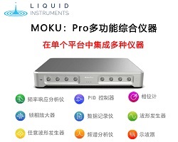
接解调幅度和相位调制信号。内部和外部参考用户可以使用内部或外部参考解调输入信号。在内部模式下,正交参考信号是用内部直接数字合成器 (DDS) 生成的。在外部模式下,用户可以选择直接或锁相选项。直接外部模式下,使用单相解调 (X) 的参考输入信号对输入信号进行解调。锁相环选项可重构两个正交参考,与参考输入信号锁相,以支持外部双相解调 (XY/Rθ)。此外,可以绕过混频器以进行其他闭环控制应用。集成PID控制器、示波器和数据记录器使用Moku锁相放大器的集成双通道、125MSa/s示波器,一次可同时监测两个信号,并用其内置的数据记录器以高达1MSa/s的速度连续记录数据。此外,PID控制器具备可实 ...
10MHz的相位调制信号以单相和双相模式输入Moku:Pro的锁相放大器和相位表。相位检测的输出通过示波器进行记录。图3:Moku:Pro上的MIM设置,用于测试不同相位检测器的线性动态范围。归一化的相位输出(作为模拟信号)绘制成图4中相移的函数。从图4(a)来看,双相解调模式下的相位表和锁相放大器都在360°范围内提供线性相位响应。单相模式下的锁相放大器只提供了90°内的近线性响应。双相解调器将相位包裹在±180°,而PLL在整个720°的相位移动范围内持续线性输出(图4(b))。图4:Moku相位表的输出,锁相放大器在单、双相位模式下的输出在(a)360°和(b)720°的相移的函数。使用 ...
4004 型相位调制器的 30 pF。信号发生器和频率合成器通常具有 50Ω 的输出阻抗,并且未针对驱动容性负载进行优化。然而,由于 30 pF 是一个相当小的电容,因此大多数信号发生器在低频 (<10 MHz) 和小信号电平下都是足够的驱动器。为驱动容性负载而优化的高压放大器也可用于有效驱动调制器。在高频下,传输调制信号的电缆和调制器之间的阻抗不匹配会导致一部分射频信号反射回信号源。8 在信号源和调制器之间插入一个定向耦合器,如图 4 所示,可用于将反射功率重定向到匹配的终结器,从而保护信号源。用与调制器输入并联的 50W 负载端接驱动调制器的线路是改善系统阻抗匹配的简单方法。在相位调 ...
这意味着总的相位调制为4π或1094纳米。这些极值出现的电压是通过对极值附近的三个点进行拟合抛物线来找到的,这增加了精度,并充分利用了SLM的16位控制。然后,强度被分为四段,用公式(11)的逆值对这些段进行缩放并转换为相位。相位响应被用来为每个SLM像素构建一个单独的查找表(LUT),以补偿SLM的非均匀性。LUT参数在SLM上平滑变化,并与肉眼可见的法布里-珀罗条纹大致对应,表明相位响应的差异是由于液晶层厚度的变化造成的。额外的像素与像素之间的变化可能来自底层硅开关电路的像素与像素之间的变化。完整的校准需要大约5分钟(在四核3.3GHz i7处理器上的3分钟扫描和2分钟计算时间),但原则上 ...
器通过精细的相位调制可以产生多光阱,从而对微粒实时操控,由此发展了全息光镊技术。美国Meadowlark Optics 公司专注于模拟寻址纯相位空间光调制器的设 计、开发和制造,有40多年的历史,该公司空间光调制器产品广泛应用于自适应光学,散射或浑浊介质中的成像,双光子/三光子显微成像,光遗传学,全息光镊(HOT),脉冲整形,光学加密,量子计算,光通信,湍流模拟等领域。其高分辨率、高刷新率、高填充因子的特点适用于生物成像及微操纵的工程中。图1. Meadowlark 2022年最新推出 1024 x 1024 1K刷新率SLM二、空间光调制器在STED超分辨中的技术介绍普通的远场荧光显微镜,使 ...
进行射频电光相位调制,然后将调制后的激光信号经过偏振分束棱镜(PBS)与四分之一波片(λ/4)进入光学腔,然后通过反射到达光电探测器,偏振分束棱镜(PBS)与四分之一波片(λ/4)的作用就是让腔反射光进入探测器。然后对反射光信号进行相位解调,得到反射光中的频率失谐信息,产生误差信号,然后通过低通滤波器和PID(比例积分电路)处理后,反馈到激光器的压电陶瓷或者声光调制器等其他响应器件,进行频率补偿,最终实现将普通激光锁定在超稳光学腔上。关于PDH技术的理论细节可以在一些综述论文和学位论文中找到。为了实现PDH锁定,需要一些专用的和定制的电子仪器,包括信号发生器,混频器和低通滤波器。Moku的激光 ...
个射频电光的相位调制,经过调制后的信号,再经过一个PBS(偏振分束镜)和一个波片((λ/4)进入我们的超稳腔与超稳腔进行谐振,反射出来的光再次经过偏振分束镜和波片被反射到光电探测器中,然后对其进行相位解调后得到误差信号,误差信号通过混频器以及低通滤波器进行处理后,得到的信号反馈到激光器的压电陶瓷或其他响应部件进行补偿频率,最终实现激光器另一路激光输出频率的稳定。PDH稳频技术的核心是通过光学超稳腔产生一个误差信号,其核心部件就是光学超稳腔,超稳腔的性能直接影响了最终输出的激光频率的稳定性。所以光学超稳腔的选择显得尤为重要。在为您的应用选择理想的腔体设计时要考虑的因素包括:线宽:在稳频激光器系统 ...
的数量级和仅相位调制模式,可以达到大多数应用所需的动态范围。其他设备,例如数字微镜设备 (DMD),具有高达数十 kHz 的刷新率和幅度调制模式,可能接近实时响应。此外,可变形反射镜提供了校正光束波前的可能性。本文提出的校准方法将应用于仅相位 SLM。以前的设备通常需要复杂的校准程序。在液晶 SLM 的情况下,完全校准可以将自己的 SLM 视为相位延迟器 - 旋转器系统,它通常表现出耦合的相位和偏振调制。在这种情况下,作为扭曲角和双折射函数的扭曲向列液晶显示器的特征值和特征向量的理论表达式已被推导出 。在这份手稿中,作者还讨论了实现仅幅度调制以及耦合幅度和相位调制的技术。使用琼斯矩阵描述其偏振 ...
或 投递简历至: hr@auniontech.com