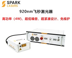
,可以发生自相位调制,四波混频,孤子自频移和超连续等多种非线性效应,这些效应都可以使飞秒激光器输出的光脉冲从单一波长变换到紫外至红外波段。特别值得提出的是,太赫兹波这一在大分子领域极具应用价值的亚毫米波长的辐射,在人类征服了X射线-紫外-可见-红外-无线电波的漫长时间后,终于在20世纪80年代,借助飞秒激光技术,实现了10um-3 mm波段的相干辐射。飞秒激光覆盖光谱范围极广的另一层含义是,飞秒脉冲内包含着数量极大的分立的相干光谱成分。一个脉冲宽度数十飞秒的脉冲可以包含高达百万个频谱成分,相当于上百万个具有不同中心波长的保持相等频率间隔的连续波激光器。图2.飞秒激光器在切割材料示意图结语:高功 ...
件相结合,将相位调制转换为损耗调制,以减少亚兆赫兹反馈带宽下的这些不良影响。Menlo Systems在2015年展示了一种带有两个快速电光致动器的腔体,尽管他们没有给出腔体的细节[37,38]。本文提出了一种在掺铒光纤OFC系统中抑制相位噪声的方案。采用两个EOMs作为快速执行器,扩展了锁相反馈带宽,克服了腔动力学的限制。在谐振腔设计中,两种电磁谐振器使用不同的调制模式来降低串扰,达到了优化的目的。实现了在CEO频率和重复频率下都具有长期稳定和超低相位噪声性能的OFC。稳定的环内显示在1 s平均时间下的分数不稳定性为积分剩余相位噪声为86.1 mrad (1Hz-1.5 MHz)。在1 s平 ...
,而且得到的相位调制特性结果为整个LCOS液晶层表面的平均结果,无法通过该方法得到液晶层特定表面的调制结果。马赫-曾德干涉方法图2马赫-曾德干涉方法原理图如图2所示。激光经过第一个BS后将光分成两路,一路光由反射镜反射到第二个BS,另一路光透过液晶空间光调制器发生调制后,与参考光干涉。得到的干涉条纹的相对移动量即为液晶空间光调制器的相位调制量。马赫-曾德干涉仪通过计算干涉图的相对移动来得到液晶空间光调制器的相位调制情况。马赫-曾德干涉基于干涉原理进行测量,但是由于装置需要的参考光为严格的平面波,对实验装置的稳定性要求较高,此外该方法适用于测量透射式液晶空间光调制器。径向剪切干涉方法径向剪切干涉 ...
光频梳的正弦相位调制干涉绝对距离测量方法研究[D].浙江理工大学,2018.[3] 姚启钧.光学教程[M].北京: 高等教育出版社, 1981更多详情请联系昊量光电/欢迎直接联系昊量光电关于昊量光电:上海昊量光电设备有限公司是光电产品专业代理商,产品包括各类激光器、光电调制器、光学测量设备、光学元件等,涉及应用涵盖了材料加工、光通讯、生物医疗、科学研究、国防、量子光学、生物显微、物联传感、激光制造等;可为客户提供完整的设备安装,培训,硬件开发,软件开发,系统集成等服务。您可以通过我们昊量光电的官方网站www.auniontech.com了解更多的产品信息,或直接来电咨询4006-888-532 ...
转。另外一种相位调制椭偏仪(PME),没有活动部件因此测试较快但是也较昂贵。在位光谱椭偏测量的数据采集方式决定了测量间隔和测量精度。光电二极管阵列可以在积分模式下进行完全并行的数据采集,而后续的相位调制椭圆仪采用串行数据采集。一个旋转偏振器多通道椭偏仪(RPE)允许在25ms时间采集64个光谱位置(ψ,Δ)点。综上所述,当测试薄膜的表面或厚度改变时,椭偏仪测试得到的椭偏参数会随之改变。椭偏仪在位监控是在进行物理或化学变化的同时对实验样品进行实时的椭偏仪测试,从而获取实验样品实时的厚度、光学常数等物理特性。下面是椭偏仪在位监控的案例。了解更多椭偏仪详情,请访问上海昊量光电的官方网页:https: ...
拉曼散射、自相位调制、四波混合、调制不稳定性、交叉相位调制、孤子动力学(孤子裂变和孤子自频移)和色散波的产生。尽管超连续谱生成背后有复杂的基础物理学,但中红外超连续谱生成的实际实现相对简单。图1说明了这一点,并描述了商用氟纤维(InF3)超连续介质发生器的概念原理和系统架构。开发了如图1所示的系统。图1所示。基于InF3光纤系统的中红外超连续介质源的基本方案和工作原理示例:所示发射光谱对应于商用超连续介质发生器(Thorlabs, SC4500,光纤长度为50厘米,重复频率为50 MHz,平均输出功率为300 mW);模拟了泵浦脉冲在200 cm长度InF3光纤上的光谱演化,说明了泵浦脉冲的产 ...
)进行二进制相位调制。它是一种基于硅基底的铁电液晶技术2K (2048 x 2048像素)反射铁电液晶硅(FLCOS),适用于成像或投影的二进制调幅的数字控制微显示器。微显示器是一种光电器件,它以二维二进制数组作为输入,并将其映射到相应的像素数组。每个像素可以根据相应输入位的值“开”或“关”,如果把开比作1,把关比作0,在0与π/2的相位转换下,它所做的是零一之间的转换。高像素分辨率2K(2048*2048)微型显示器示意图:像素截面俯视结构示意图:流程:入射光—上层玻璃—前电极—像素镜面-反射光工作原理图示意:液晶反转图:Forth Dimension Displays使用时域成像技术,可以 ...
方式,PM:相位调制方式。图5:时间序列(上轴)样例,同时它相对应的Allan标准差图(下轴)。针对多个平均时间τ进行评估,结果以log - log刻度显示。图6:幂定律噪声源在Allan标准差图上显示为已知的斜率,让我们可以容易地对系统噪声建模。总的噪声定义为不相干的独立噪声分布总和,即。在这种情况下,稳定性随着平均时间的推移而提高(因为白噪声的影响减少),直到粉红/闪烁噪声成为主导。 在较长的时间尺度上,稳定性受到数据线性漂移的限制(参见图5,上轴)。 当平均时间约为5000秒时,测量结果很稳定。如何在Moku配置Allan方差测量下方视频演示如何在Moku配置Allan方差测量。视频链接 ...
关系。图2:相位调制器图3:相移这相当于几伏特,在给定的电极几何形状下;对于较长的波长,它比较短的波长要高,例如,可以期望在红色区域为3V(635nm),在电信波长范围内(约1550 nm)为10 V。由于非常快速的电光响应,较低的控制电压和使用复杂的电极几何形状,它可以在千兆赫兹范围内的频率上实现调制。将相位调制器插入集成的Mach-Zehnder干涉仪中,形成调幅器。图4:Mach-Zehnder振幅调制器施加电压会导致分支之间的相对相位差,从而通过干扰导致器件输出处的输出功率的变化。因此,设备传输可以控制在min值和max值(P min到Pmax)之间。从打开状态到关闭状态切换需要π的相 ...
。电磁场引起相位调制,通过马赫-曾德尔干涉仪结构转换为强度调制信号。对于MZICR型器件,不仅可以获得略高的灵敏度,而且可以采用平衡检测方案来降低噪声。此外,与简单的微环设备相比,控制激光波长以匹配谐振器的共振更容易,因为有两个输出可用。然而,所有基于谐振的器件在调制带宽方面都有固有的限制,其近似等于谐振器线宽。3.制作过程基于TFLN平台的光学Mach-Zehnder调制器的制作流程如图3.10,13所示。TFLN平台是通过使用晶体离子切片方法将薄层铌酸锂转移到石英衬底上实现的,如图3(a)和3(b)所示。将大块铌酸锂晶体离子注入并结合到石英衬底上。随后的加热过程将一层薄薄的铌酸锂转移到石英 ...
或 投递简历至: hr@auniontech.com